Loudspeaker Test Box
Introduction
Testing loudspeakers is covered in some detail in the passive crossover article (see Design of Passive Crossovers), but it is irksome at best to have to fiddle about with clip leads and components lying all over the workbench. This simple project is intended to make life that little bit easier when you are trying to determine the optimum frequency compensation network for woofers and midrange drivers.
Description
They don't come much simpler than this. A suitable plastic box, a couple of switches, 4 combination binding posts / banana sockets, a handful of capacitors and a wirewound pot complete the entire project.
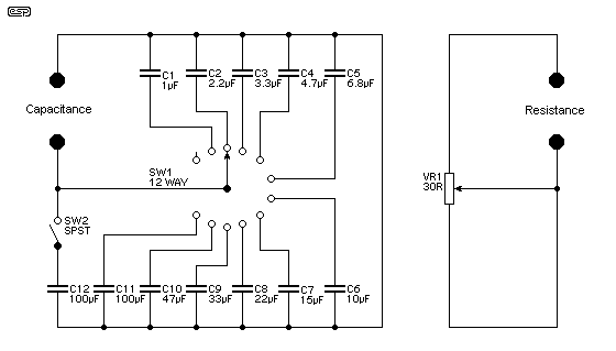
Of all the components, the pot is most likely to cause problems. The suggested value of 30 Ohms was used in my case because I just happened to have one lying around in my junk box, but they don't seem to be easy to get. A very basic tweeter attenuator may work OK, and the value is not that important. Even a resistance as low as 8 Ohms could be used, with a switchable 8.2 Ohm resistor in series so that the range will be from 0 to 16 Ohms (near enough). I shall leave it to the individual to determine the best way to achieve the required range, which is typically 0 to 20 Ohms.

Figure 1 - Complete Circuit of Test Box
The switch SW2 and associated 100uF cap is optional, and increases the range up to 200uF - in most cases this won't be necessary though. The caps are all bipolar electrolytics, and this is perfectly OK, since they will not be used at high power, and their sonics are not important (assuming that you can hear the difference anyway).
To use the box, simply connect it across the speaker - mostly you will want the caps and pot in series, so a lead between the two (or even a switch) makes this easy. From the output of suitable small amplifier, place a 100 ohm or so resistance in series with the output. Sweep the signal frequency across the speaker. Resonance will not be affected, but there will be a "magic" combination of capacitance and resistance that will make the impedance above resonance completely flat. No maths, no spreadsheets, just a quick frequency scan and twiddle a couple of knobs to get the values needed to ensure that the crossover actually will work at the design frequency.
The network derived from the testing will be placed in parallel with the speaker, and prevents the rise of impedance with increasing frequency. This rise is caused by the inductance of the voice coil, and plays havoc with the performance of any passive crossover network.
Impedance Measurements
One of the most difficult measurements to make in audio is impedance, but this is also made relatively simple. Carefully measure the voltage across the speaker at the crossover frequency - this will (of course) be the same as the voltage anywhere else outside of the resonance affected area of the impedance plot.
Disconnect the speaker, and without changing anything, connect the pot (all by itself) instead. Adjust the pot until the voltage is exactly the same as you measured before, when the speaker and parallel network were in place. Disconnect the amp, and measure the resistance of the pot - this is the speaker impedance, and this is the real impedance - not the "nominal" impedance. It is the actual measured impedance that must be used to calculate the crossover network components.
Don't change the frequency from the generator or the amp level just yet ...
In many (OK, all) cases, it is highly recommended that the tweeter is also measured for impedance, and a resistance used in parallel so that the impedance at crossover exactly matches that of the woofer or midrange driver. Simply connect the tweeter across the amp, with the pot in parallel. Carefully adjust the pot until the voltage is exactly the same as that measured before (this is where a pot that goes up to about 30 Ohms is useful). When the voltage is the same, disconnect the amp and tweeter, and measure the setting of the pot. This is the resistance that should be used in parallel with the tweeter to make everything work properly.
This is a simple procedure that works extremely well, and my test box has been used quite a few times in the short time I have had it. The measurements described in the Design of Passive Crossovers article work well, but this is much quicker, and is "real", in that you can see the effect of varying resistance or capacitance easily. There will nearly always be a compromise in the crossover design, and this little test box lets you see exactly what happens, and select the best possible combination for the speaker drivers you are using.
Title: Loudspeaker Test Box
electronic circuit
Source: unknown
Published on: 2012-09-20
Reads: 343
Print version: ![]()
Other electronic circuits and schematics from Audio
-
Headphone Amplifier
-
Band 2 Preamplifier
-
Low impedance microphone amplifier
-
Sound Pressure Level Meter
-
Stereo Tone Control
-
Balanced Low Noise Microphone Preamp
-
Low cost intercom using transistors
-
Speech Recorder
-
25W Mosfet audio amplifier
-
Two transistor audio amplifier circuit
